Datsun Roadster Parts
from Rallye Enterprises, Ltd.
|
|
68-70 IGNITION SWITCH INFORMATION |
||
|
|
|
|
|
Not Currently Available |
Not Currently Available |
Not Currently Available |
|
487-06 |
487-05 |
487-08 |
|
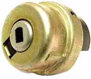
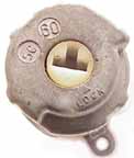
This switch is easy to identify from the unique coupling design where it meets the lock cylinder. The wiring pattern of the 5 terminals on this switch is: R A
|
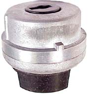
The original switch had a very short guide rail. (see arrow) It was designed for a lock housing that had a very short "slot" for this rail. This switch can also be used on the lock housing that has the full length slot. NOTE: The current replacement switch that is coming from Japan is the same switch, with the same wiring pattern, but the short stubby guide rail (arrow in pic above)is full length like the 487-08 switch on the right. If you need this switch with the stubby rail, with the below wiring pattern you will have to carefully file down this guide rail so it matches your old switch. The wiring pattern of the 5 terminals on this switch is: R A This item is not currently available. The 487-09 is the switch and lock assembly that can be used for this; if your old lock assy has the larger barrel size. See 487-09 listing for info. |
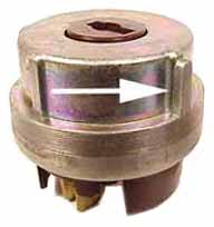
This switch has a full length guide rail for those lock housing. s that have the full length slot. This could be used on the the assy's with the short slot if the rail is carefully filed off, leaving a short rail like the 487-05 switch on the left. The wiring pattern of the 5 terminals on this switch is: A B The 4 87-09 is the switch and lock assembly that can be used for this; if your old lock assy has the larger barrel size. See 487-09 listing for info. |
|
|
|
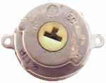
The two switches on the left are fairly rare to see in a roadster, which probably means YOU have one, right? They differ by the number of mounting screws, 1 or 2 as shown in the pictures.The wiring pattern of the 5 terminals on these two switches is: A B If yours is different the connectors in your plug in can be switched around. |
|
487-07 |
487-10 |
|
|
|
|
||

|
|